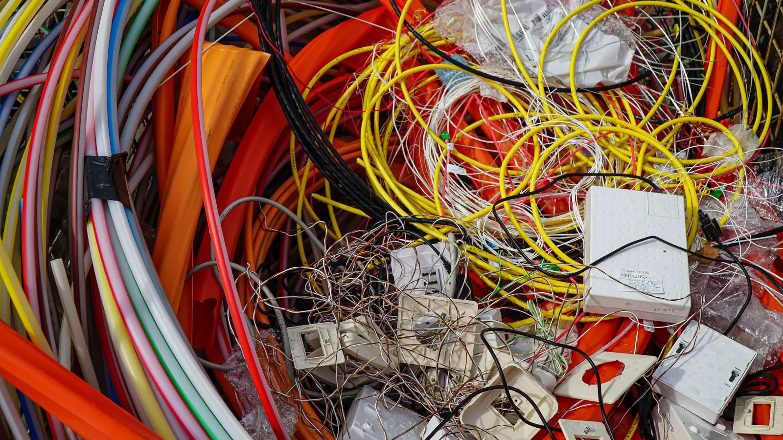
Standard cable assembly layouts offer speed and lower cost for repeatable runs, while custom layouts fit unique equipment geometries. Choose based on production volume, service access, and harness routing complexity. Evaluate both before finalizing your wire harness design.
- Standard layouts reduce engineering time when connector positions and wire lengths are consistent across units.
- Custom layouts are necessary when equipment geometry, service access, or environmental zones force non-standard routing.
- Production volume and maintenance access drive the cost and design trade-off between the two approaches.
- A hybrid model can use standardized subassemblies inside a custom overall harness assembly.
- Document connector spacing, bend radii, and strain relief locations early to avoid late redesigns.
What Defines a Standard Cable Assembly Layout
A standard cable assembly layout follows a repeatable pattern. Connectors sit at fixed distances. Wire lengths follow a base bill of materials. Routing paths avoid sharp bends and use the same strain relief method from unit to unit. This approach is common when a manufacturer ships hundreds or thousands of similar assemblies.
The design is driven by the connector catalog and the enclosure. If the connectors are the same and the equipment footprint is stable, the layout can be reused. Engineers define a base harness, then adjust wire lengths within tolerance. The production line can pre-cut, pre-terminate, and pre-route the harness without re-engineering every unit.
This method is not limited to large factories. A small machine builder can use a standard layout for a product line that runs for years. The key factor is consistency. If the next unit has the same connector positions, the same cable entry points, and the same maintenance access, a standard layout works well.
What Drives a Custom Cable Assembly Layout
A custom cable assembly layout adapts to a specific machine or installation. The connector positions may not match any catalog pattern. Wires may need to route around a motor, a pump, or a control panel that has no clear standard. The harness may need to service a component without removing other parts.
Custom layouts are common in retrofit work, prototype builds, and high-value machines. Each unit may require a different wire length, a different connector orientation, or a different routing path. The engineer must check bend radii, clearance, and strain relief for every wire. The process is slower, but it fits the equipment.
Custom layouts also appear when environmental conditions change the routing. A cable that runs in an open area may need to route under a shield. A harness that enters a wet zone may need a different entry seal. The design must account for heat, vibration, and future service access.
Standard versus Custom Cable Assembly Layout Comparison
The table below compares the main options. Use it to check which approach fits your project.
| Option | Best for | Limitations |
|---|---|---|
| Standard cable assembly layout | Repeatable production runs with consistent connector positions and low maintenance complexity | Limited flexibility for unique equipment geometries or one-off builds |
| Custom cable assembly layout | Prototypes, retrofits, and machines with non-standard routing or service access | Higher engineering time and per-unit cost, slower production |
| Hybrid subassembly layout | Products that share common subassemblies but need different overall harness routing | Requires clear modular boundaries and interface definitions |
| Parameterized standard layout | Product families with small variations in wire length or connector type | Needs disciplined engineering changes to avoid uncontrolled variation |
When to Use a Standard Cable Assembly Layout
A standard layout is the right choice when the equipment is stable and the production volume is meaningful. If you are building a conveyor, a pump skid, or a control cabinet that ships in quantity, a standard layout reduces errors. The production line can verify the same routing every time. Quality control checks become repeatable.
Standard layouts also simplify procurement. Connectors, cable, and termination materials follow a fixed list. Purchasing can commit to bulk quantities. The wire harness design remains stable, so tooling and work instructions do not change often.
This approach works best when the installation site does not vary much. If every unit goes into the same enclosure, with the same space above and below the harness, the routing plan holds. If the customer installs the machine in a tight cabinet or a different orientation, the standard layout may fail.
When to Use a Custom Cable Assembly Layout
A custom layout is necessary when the machine or installation does not follow a repeatable pattern. A retrofit that adds new sensors to an existing panel often needs new routing. A prototype that changes the motor position requires new wire lengths. A mobile machine that must service components from different access points may need a harness that bends around a frame.
Custom layouts are also needed when the harness must meet a specific maintenance requirement. If a technician must replace a pump without disconnecting the main harness, the routing must allow that access. If a wire crosses a moving part, the custom layout may need a different path.
The cost of custom work is not only engineering time. Each unit may need a separate design check. The production team may need to verify wire lengths one by one. Documentation must be more detailed. A custom layout is worth it when the risk of a poor fit is high.
How Hybrid and Parameterized Approaches Reduce Risk
Many projects sit between standard and custom. A hybrid layout uses standardized subassemblies inside a custom overall harness. For example, the power feed may use a standard subassembly, while the sensor harness uses a custom routing to reach a new sensor. The interface between the subassemblies and the main harness is defined with connector pins, wire lengths, and routing clearance.
A parameterized standard layout is another option. The base harness remains standard, but a small number of variables are allowed. Wire length can change within a range. One connector type can be swapped for another. The routing plan stays the same. This works for product families where the machine shape changes slightly but the service pattern stays the same.
Both approaches require clear engineering controls. If the parameter range is too wide, the layout stops being standard. If the interface is not defined, the subassemblies do not fit. A written design rule set keeps the hybrid approach manageable.
Practical Design Checks for Both Layout Types
Regardless of the layout type, the same checks apply. The first check is connector spacing. If the connectors are too close, the harness cannot bend without kinking. Measure the clearance between connector bodies and the enclosure wall. Leave room for the connector housing and the strain relief.
The second check is bend radius. Every wire has a minimum bend radius. A harness that routes around a frame edge may need a larger radius than the wire spec allows. Use a bend radius that meets the wire and insulation requirements. If the frame edge is sharp, add a protective sleeve or a curved guide.
The third check is strain relief. The strain relief location must match the routing. If the harness enters an enclosure, the strain relief should sit just outside the entry point. If the harness moves, the strain relief must allow movement without pulling on the connector pins.
The fourth check is maintenance access. The harness must allow a technician to reach connectors, terminals, and sensor ports. A custom layout may need extra clearance at the service side. A standard layout may need a different entry seal if the service side is exposed.
Common Mistakes in Cable Assembly Layout Decisions
The first mistake is choosing the layout after the connectors are ordered. If the connector positions are set, the routing is constrained. A late change to the connector position can force a full redesign.
The second mistake is assuming standard means simple. A standard layout still needs bend radius checks, strain relief checks, and service access checks. The only difference is that the checks are repeatable.
The third mistake is underestimating the custom work. A custom layout may look small on paper, but the engineering time can grow. Each wire path needs a drawing. Each connector needs a pinout. Each service point needs a note.
The fourth mistake is ignoring the production line. A layout that works on the bench may not work in production. If the routing requires a specific hand motion, the line may be slow. If the strain relief must be fitted in a tight space, the operator may make errors.
How to Decide Between the Two Layouts
Start with the equipment stability. If the machine design is final and the connector positions are fixed, a standard layout is a strong candidate. If the machine is still changing, a custom layout may be safer.
Next, look at production volume. A low volume run with a stable design can use a standard layout. A high volume run with a changing design needs a parameterized or hybrid approach.
Then, check maintenance access. If the harness must service components without disassembly, the routing must allow it. If the standard layout blocks access, a custom layout or a hybrid subassembly is needed.
Finally, review the cost of error. A standard layout that fits poorly can cause field failures. A custom layout that is over-engineered can add cost without value. The decision is not about which is better. It is about which fits the project.
A well-designed cable assembly layout matches the equipment, the production process, and the service plan. Standard layouts are efficient. Custom layouts are precise. The best choice is the one that keeps the harness reliable without adding unnecessary cost.
Frequently asked questions
Can a standard cable assembly layout be used for a one-off prototype?
Yes, if the prototype uses the same connector positions and routing as future production. The standard layout can save engineering time. If the prototype changes the geometry, a custom layout is better.
How do I know if my harness needs a custom layout?
Check the connector positions, the enclosure space, and the service access. If any of these differ from a repeatable pattern, the harness may need a custom layout.
What is the main cost difference between standard and custom layouts?
Standard layouts reduce engineering time and production variation. Custom layouts add engineering time and per-unit checks. The difference shows up in design hours and production verification.
Can I change from a standard layout to a custom layout after production starts?
It is possible, but it is expensive. The harness design, tooling, work instructions, and quality checks must be updated. Plan the layout before production starts.
Does a hybrid layout always require a custom subassembly?
No. A hybrid layout can use standard subassemblies with a custom routing. The interface must be defined, but the subassemblies themselves can be standard.