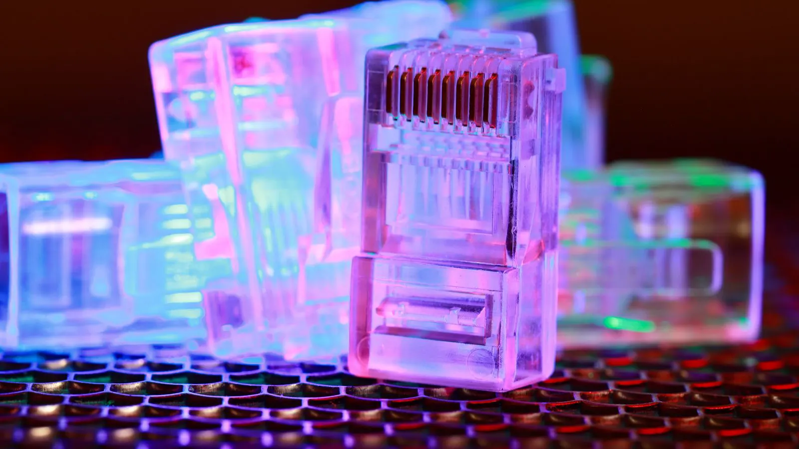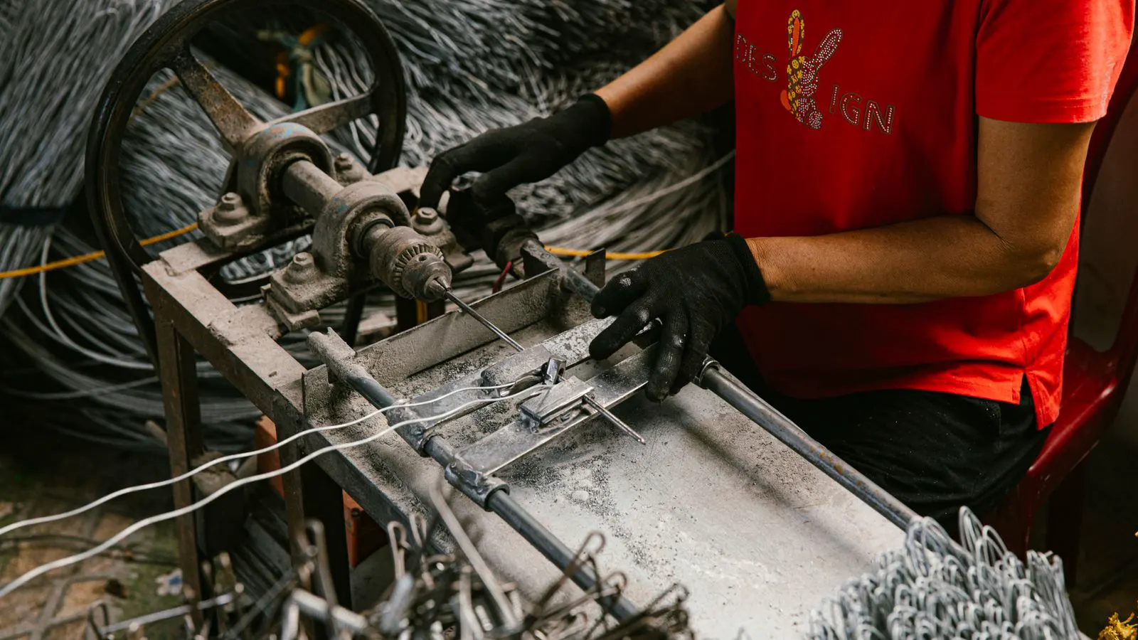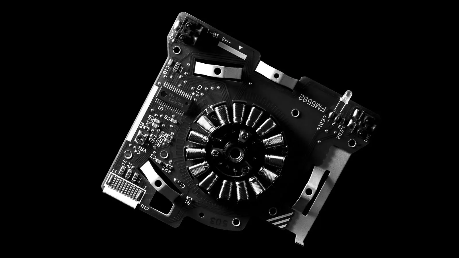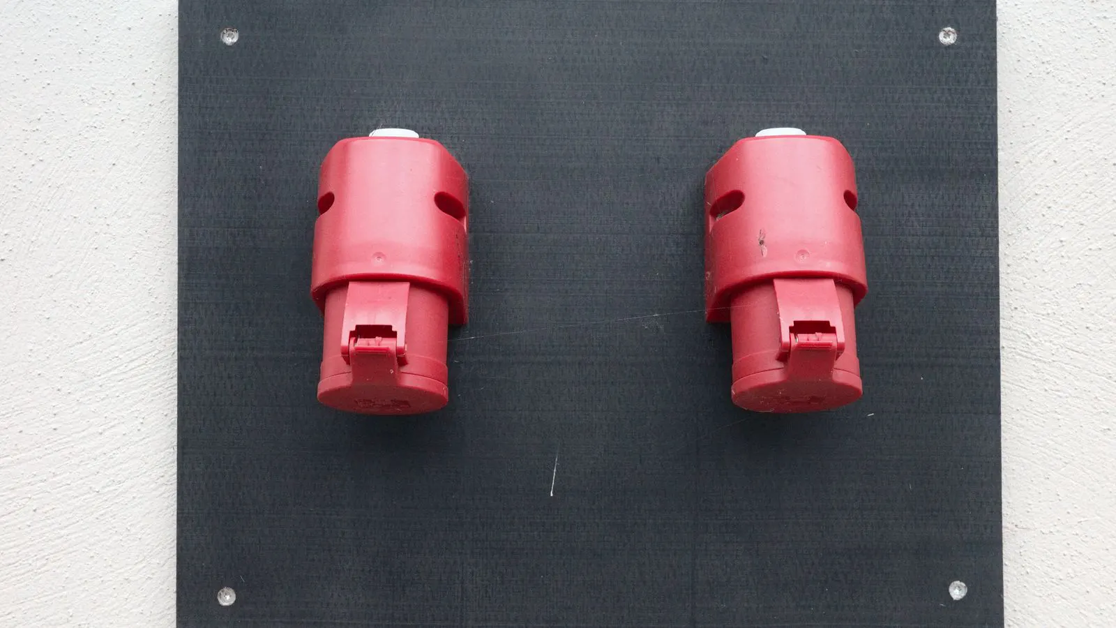
Industrial connectors support high-vibration, high-current, and high-speed applications. This guide covers common types, mating systems, and a selection table to help engineers choose reliable options for component sourcing.
- Match connector type to the application's environment, current, and signal speed.
- Verify mating system compatibility before ordering pins, housings, and housings.
- Check mechanical, electrical, and environmental ratings against the final installation.
- Confirm tooling and process fit for crimp, solder, or push-in assembly.
- Document part numbers and revision levels to simplify repeat procurement.
Industrial connectors are the electrical and mechanical junction points where a wire harness meets a board, device, or mating assembly. The right type depends on the operating environment, current load, signal speed, and the assembly method the factory can support. This guide breaks down the main industrial connector options and gives you a practical selection process.
What defines an industrial connector
An industrial connector is built to survive vibration, thermal cycling, moisture, dust, and repeated mating cycles. Unlike consumer connectors, it is usually rated for higher current, larger pin counts, and stricter environmental tolerances. The housing, contacts, and insulation are selected to match the application.
The most common design variables are pin count, contact style, housing material, and mating method. Pin count sets the number of signals or power lines. Contact style determines the current handling and signal integrity. Housing material affects temperature tolerance and corrosion resistance. The mating method determines how the harness is attached to the board or panel.
Common industrial connector types
High-density board-to-board connectors
These connectors carry multiple signals in a small footprint. They are common in control boards, power distribution units, and sensor arrays. Many use surface-mount or through-hole housings. Pin pitch is usually tight, which requires precise placement and careful inspection.
The main trade-off is signal integrity versus footprint. Tighter pitch allows more signals in a small space, but it increases sensitivity to noise and alignment errors. For high-speed digital signals, impedance control and proper grounding matter more than raw current rating.
Power distribution connectors
These connectors handle higher current with thicker contacts and larger pin bores. They are used in power supply units, motor controllers, and battery management systems. The housing is often larger, and the contacts may use gold or silver plating to reduce resistance and corrosion.
Thermal management is the key concern. A connector that passes the current rating in a lab may overheat in a dense enclosure with poor airflow. Check the maximum continuous current at the highest expected ambient temperature, not at room temperature.
DIN-style and panel connectors
These connectors mount to a panel or backplane and provide a reliable mechanical lock. They are common in machine control, industrial Ethernet, and fieldbus applications. The housing is usually metal or high-heat thermoplastic.
The advantage is vibration resistance and a secure connection. The disadvantage is size and the need for panel clearance. In high-vibration machines, a panel-mounted connector with a locking tab often outperforms a direct board-to-board connection.
High-speed interface connectors
These connectors are designed for data rates above typical analog or low-speed digital levels. They use controlled-impedance contacts, precise pin geometry, and often differential signaling. The housing is sized to maintain consistent spacing between signal and ground pins.
The main failure modes are crosstalk, reflection, and contact oxidation. For high-speed applications, the connector is only as good as the trace design, grounding plan, and mating repeatability. A poor mating angle can introduce signal loss even in a well-designed connector.
Crimp and solder-compatible connectors
Some industrial connectors use crimp terminals, others use solder tabs, and some accept both. The choice is driven by the assembly line. Crimp connectors are faster for high-volume work and use less heat. Solder connectors can be more reliable in high-vibration environments if the joint is properly tinned and inspected.
The selection depends on the wire gauge, the contact material, and the process control. A crimp contact that is undersized for the wire will fail under vibration. A solder joint that is cold or contaminated will have higher resistance than specified.
Mating systems and mechanical compatibility
Mating system is the mechanical and electrical interface between the connector housing and its pins, terminals, or board. The same connector part number may not be compatible with a different series even if the pin count looks identical.
Check the following before ordering:
- Pin pitch and row count. A one-pin offset can cause short circuits.
- Contact material and plating. Gold, silver, and tin have different resistance and corrosion characteristics.
- Mating depth and alignment features. Some connectors require a keyed housing or a specific insertion angle.
- Retention method. Snap-fit, screw, and locking-tab designs all have different vibration performance.
- Wire entry and strain relief. A connector that holds the wire poorly will fail at the entry point, not at the contact.
A common mistake is mixing housings from different series with the same pin count. The outer dimensions may look similar, but the internal contact spacing can be different. Always verify the mating part number from the supplier catalog or the drawing.
Electrical and environmental selection criteria
The table below lists the main criteria to evaluate when selecting industrial connectors for a harness.
| Criterion | What to look for | Why it matters |
|---|---|---|
| Current rating | Continuous current at maximum ambient temperature | Prevents overheating and contact degradation |
| Insulation resistance | Minimum resistance between conductors and housing | Protects against leakage and ground faults |
| Dielectric strength | Voltage withstanding without breakdown | Ensures safe operation under transient spikes |
| Vibration rating | Acceleration and frequency range tested | Maintains contact integrity in moving machines |
| IP rating | Protection against dust and water | Determines suitability for outdoor or wet areas |
| Operating temperature | Minimum and maximum housing and contact temperature | Affects insulation life and contact resistance |
| Mating cycles | Number of openings and closings rated | Shows long-term reliability in service |
| Signal integrity | Insertion loss, return loss, crosstalk | Critical for high-speed or precision signals |
A connector that meets the electrical ratings but fails the vibration test will eventually lose contact. A connector that passes vibration but has low insulation resistance will leak current in a damp environment. The ratings must be checked together, not in isolation.
Assembly process and tooling
The assembly method changes the cost, speed, and reliability of the final harness. Crimping requires a calibrated tool, a verified die, and a process inspection point. Soldering requires a controlled reflow or wave process, proper flux, and a visual or X-ray inspection for fine-pitch parts. Push-in or press-fit connectors are faster but can be less repeatable in high-vibration applications.
The process choice is often driven by the wire gauge and the pin count. Thin gauge wire with high pin density is difficult to crimp cleanly. Large gauge power wire is easier to crimp but needs a larger contact and housing. The tooling must match the wire and the connector contact.
A practical check is to run a small sample batch through the full process. Inspect the crimp height, the solder fillet, and the contact seating. A connector that looks good on the bench may fail after thermal cycling if the contact is not fully seated.
Sourcing and documentation
For component sourcing, the most useful documents are the datasheet, the mechanical drawing, and the mating compatibility list. The datasheet gives electrical and environmental ratings. The drawing gives dimensions, pinout, and mounting features. The compatibility list tells you which housings, pins, and terminals work together.
Keep a controlled part number list for each project. Include the revision level, the plating finish, and the packaging. A connector with the same base number but a different revision may have a changed contact material or a different housing thickness. This change can affect assembly tooling and inspection.
When working with a supplier, ask for the process capability data on the mating cycle and the contact resistance. A general “tested to standard” statement is not enough. You need to know the measurement method and the acceptance limits.
Final selection checklist
Use this checklist before placing a purchase order.
- Confirm the application voltage, current, and signal speed.
- Match the connector type to the environment and vibration level.
- Verify the mating system and pinout against the drawing.
- Check the electrical ratings at the maximum expected temperature.
- Confirm the assembly process and tooling are available.
- Review the environmental and mechanical ratings for the final installation.
- Document the part number, revision, and supplier lot.
- Run a sample batch through the full assembly and inspection process.
A well-chosen industrial connector reduces field failures and simplifies maintenance. The goal is not the cheapest connector on the bench. It is the connector that stays reliable through the expected life of the machine.
Frequently asked questions
What is the main difference between a high-speed connector and a power connector?
A high-speed connector is designed for signal integrity at high data rates, with controlled impedance and tight tolerances. A power connector is designed for high current with thick contacts and larger pin bores.
Can I use a crimp connector in a high-vibration application?
Yes, if the crimp is made with the correct tool and process, and the connector has a retention feature. The contact must be verified for vibration performance, not just electrical ratings.
How do I know if two connectors are compatible?
Check the mating part number, pin pitch, row count, and housing dimensions. The same pin count does not guarantee compatibility.
What should I check before ordering a connector for a wet environment?
Check the IP rating, insulation resistance, and contact plating. A low IP rating or a poor plating finish will cause leakage and corrosion.
Does the wire gauge matter for connector selection?
Yes. The wire gauge must match the contact size and the process. An undersized wire will not crimp correctly, and an oversized wire will not seat in the contact.